概述 上一篇post讲述了单周期CPU的简单实现 ,在这篇post我将会讲述单周期CPU的烧板过程。在进行仿真测试后,验证了单周期CPU的正确性之后,我们就可以将CPU烧到Basy3板中了。
原理 使用数码管显示我们需要的一些信息,如当前PC、下一条PC、寄存器号、寄存器内容等。要求如下:四位的移位寄存器 ,高频率地扫描显示我们需要的信息。根据Basy3板提供的是一个500MHz的时钟信号,这个信号用于扫描显示频率太高了,因此我们需要写一个分频器 。为了在七段数码管上显示,我们还需要写一个译码显示的译码器 。最后,CPU的工作时钟是由我们通过按键手动输入的,因此对于按键产生的信号需要做消抖处理 。
代码实现 1.四位的移位寄存器(counter4.v) 这里是需要做四位的计数功能,因此我们可以手动编写状态转移。
1
2
3
4
5
6
7
8
9
10
11
12
13
14
15
16
17
18
19
20
21
22
23
24
25
26
27
module counter4( input clk, input reset, output reg [3 :0 ] count ); reg [3 :0 ] count; initial begin count <= 0 ; end always @(posedge clk or negedge reset) begin if (reset == 0 ) begin count <= 4'b0000 ; end else begin if (count == 4'b0000 ) count <= 4'b1110 ; else if (count == 4'b1110 ) count <= 4'b1101 ; else if (count == 4'b1101 ) count <= 4'b1011 ; else if (count == 4'b1011 ) count <= 4'b0111 ; else if (count == 4'b0111 ) count <= 4'b1110 ; end end endmodule
2.时钟分频器(clock_div.v) 从Basy3板提供的高频时钟中分离出一个用于扫描显示的频率,大概是100Hz左右.
1
2
3
4
5
6
7
8
9
10
11
12
13
14
15
16
17
module clock_div( input clk, output reg clk_sys = 0 ); reg [25 :0 ] div_counter = 0 ; always @(posedge clk) begin if (div_counter == 50000 ) begin clk_sys <= ~clk_sys; div_counter <= 0 ; end else begin div_counter <= div_counter + 1 ; end end endmodule
3.显示译码器(7_SegLED.v) 显示译码需要对照Basy3板中七段管接口,对于每一个需要显示的数字,适当地设置对应的显示代码,注意是低电平点亮 。
1
2
3
4
5
6
7
8
9
10
11
12
13
14
15
16
17
18
19
20
21
22
23
24
25
26
27
module 7_ SegLED( input [3 :0 ] display_data, output reg [7 :0 ] dispcode ); always @( num ) begin case (num) 4'b0000 : dispcode = 8'b1100_0000 ; 4'b0001 : dispcode = 8'b1111_1001 ; 4'b0010 : dispcode = 8'b1010_0100 ; 4'b0011 : dispcode = 8'b1011_0000 ; 4'b0100 : dispcode = 8'b1001_1001 ; 4'b0101 : dispcode = 8'b1001_0010 ; 4'b0110 : dispcode = 8'b1000_0010 ; 4'b0111 : dispcode = 8'b1101_1000 ; 4'b1000 : dispcode = 8'b1000_0000 ; 4'b1001 : dispcode = 8'b1001_0000 ; 4'b1010 : dispcode = 8'b1000_1000 ; 4'b1011 : dispcode = 8'b1000_0011 ; 4'b1100 : dispcode = 8'b1100_0110 ; 4'b1101 : dispcode = 8'b1010_0001 ; 4'b1110 : dispcode = 8'b1000_0110 ; 4'b1111 : dispcode = 8'b1000_1110 ; default : dispcode = 8'b0000_0000 ; endcase end endmodule
4.消抖模块(key_fangdou.v) 这一部分代码是从网上找的,基本上都可以直接搬过来用。
1
2
3
4
5
6
7
8
9
10
11
12
13
14
15
16
17
18
19
20
21
22
23
24
25
26
27
28
29
30
31
module key_fangdou(clk,key_in,key_out);parameter SAMPLE_TIME = 4 ;input clk;input key_in;output key_out;reg [21 :0 ] count_low;reg [21 :0 ] count_high;reg key_out_reg;always @(posedge clk)if (key_in ==1'b0 )count_low <= count_low + 1 ; else count_low <= 0 ; always @(posedge clk)if (key_in ==1'b1 )count_high <= count_high + 1 ; else count_high <= 0 ; always @(posedge clk)if (count_high == SAMPLE_TIME)key_out_reg <= 1 ; else if (count_low == SAMPLE_TIME)key_out_reg <= 0 ; assign key_out = key_out_reg;endmodule
5.烧板顶层模块(display_cpu.v) 与CPU顶层模块类似,在这一模块中连接各个模块,设置不同拨码开关状态情况下显示的内容。
1
2
3
4
5
6
7
8
9
10
11
12
13
14
15
16
17
18
19
20
21
22
23
24
25
26
27
28
29
30
31
32
33
34
35
36
37
38
39
40
41
42
43
44
45
46
47
48
49
50
51
52
53
54
55
56
57
58
59
60
61
62
63
64
65
66
67
68
69
70
71
72
73
74
75
76
77
module display_cpu( input clock, input reset, input button1, input button2, input btn, output [3 :0 ] select, output [7 :0 ] dispcode, output testsignal ); wire [3 :0 ] pos1; wire [3 :0 ] pos2; wire [3 :0 ] pos3; wire [3 :0 ] pos4; wire clk_sys; wire [2 :0 ] count; wire [31 :0 ] pc; wire [31 :0 ] pcnext; wire [5 :0 ] Opcode; wire [31 :0 ] result; wire [4 :0 ] rs; wire [4 :0 ] rt; wire [31 :0 ] Data1; wire [31 :0 ] Data2; wire [31 :0 ] DataOut; reg [3 :0 ] num; wire clk; wire testsignal; assign testsignal = btn; counter4 U0(clk_sys, reset,select); clock_div U1 (clock,clk_sys); key_fangdou f(clock, btn, clk); display dis (num, dispcode); assign pos1 = (button1 ? (button2 ? result[7 :4 ] : rt[4 ]) : (button2 ? rs[4 ] : pc[7 :4 ] )); assign pos2 = (button1 ? (button2 ? result[3 :0 ] : rt[3 :0 ]): (button2 ? rs[3 :0 ] : pc[3 :0 ] )); assign pos3 = (button1 ? (button2 ? DataOut[7 :4 ] : Data2[7 :4 ]) : (button2 ? Data1[7 :4 ] : pcnext[7 :4 ])); assign pos4 = (button1 ? (button2 ? DataOut[3 :0 ] : Data2[3 :0 ]): (button2 ? Data1[3 :0 ] : pcnext[3 :0 ])); s_cpu uut (clk, reset, Opcode, Data1, Data2, pc, pcnext, result, rs, rt, DataOut); always @(select) begin case (select) 4'b1110 : begin num = pos4; end 4'b1101 : begin num = pos3; end 4'b1011 : begin num = pos2; end 4'b0111 : begin num = pos1; end endcase end endmodule
测试运行 烧板前最好先自己编写测试仿真文件来验证是否正确,这样可以节省时间提高效率,这里就直接给出我写的测试文件。特别注意,测试的时候不需要分频器。
1
2
3
4
5
6
7
8
9
10
11
12
13
14
15
16
17
18
19
20
21
22
23
24
25
26
27
28
29
30
31
32
33
34
35
36
37
38
39
40
41
42
43
44
45
46
47
48
module test2; reg clk; reg CLK; reg reset; reg button1; reg button2; wire btn; wire [3 :0 ] select; wire [7 :0 ] dispcode; reg [7 :0 ] c; display_cpu t ( .clock (CLK), .reset (reset), .button1 (button1), .button2 (button2), .btn (clk), .select (select), .dispcode (dispcode) ); initial begin clk <= 0 ; reset <= 0 ; button1 <= 1 ; button2 <= 1 ; CLK <= 0 ; c <= 0 ; #1 ; reset <= 1 ; forever #4 begin CLK = ~CLK; if (c>6 ) begin c <= 0 ; clk = ~clk; end else c <= c + 1 ; end end endmodule
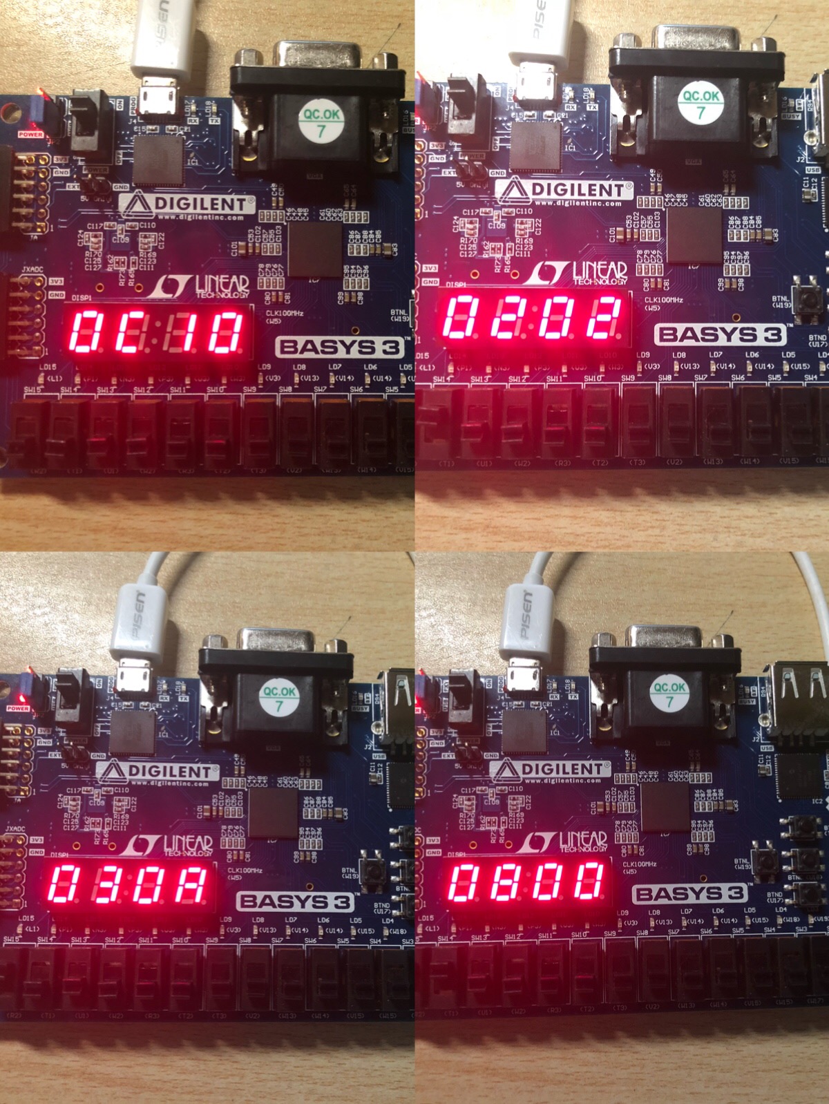
完成后就可以将CPU烧写进Basy3板中,运行就可以了。每次运行前记得先在重置状态下先按一下,给CPU一个时钟脉冲进行初始化。
小结 烧板不是必做的内容,但是如果有时间的话还是建议大家去做。虽然分数不会差很多,但是整个过程下来会加深自己的理解,也让自己学到更多关于硬件编程方面的知识。单周期CPU的烧板部分就讲解到这里了,谢谢!